Modbus connection parameters

- Byte Order:
- Little Endian
- The least significant byte is stored first (e.g.
0x1234→34 12)
- The least significant byte is stored first (e.g.
- Big Endian
- The most significant byte is stored first (e.g.
0x1234→12 34)
- The most significant byte is stored first (e.g.
- Little Endian
- Bit Order:
- Standard
- Bits are ordered from the most significant bit (bit 7) to the least significant bit (bit 0).
Example:0b10000000→ bit 7 is1, bit 0 is0.
- Bits are ordered from the most significant bit (bit 7) to the least significant bit (bit 0).
- Reverse
- Bits are ordered from the least significant bit (bit 0) to the most significant bit (bit 7).
Example:0b10000000→ bit 0 is1, bit 7 is0.
- Bits are ordered from the least significant bit (bit 0) to the most significant bit (bit 7).
- Standard
- Maximum Data Gap / Maximum Data Lenght
- Length
- Defines the maximum number of words that can be read from the device in a single operation. Some smaller sensors have a limit on the number of words that can be read at once.
- Gap
- Used for optimization. It specifies the maximum allowed gap between data blocks to be read continuously. Adjusting this value may affect reading performance, but it is generally recommended to leave it unchanged.
- Length
- Max wait time
- Specifies max wait time to receive value – the time for which will DataTalk wait for response from PLC adjust this according to your network speed and PLC capatabilities
- Single value write only:
- This option switches between multiple write class and single write class
FC5 “Force Single Coil” & FC6 “Preset Single Register” X FC15 “Force Multiple Coil” & FC16 “Preset Multiple Registers”
Address mapping
In our system, we use a short or symbolic addressing format to simplify working with Modbus registers. For example:
- H:0 refers to Modbus address 40001
- H:1 = 40002, H:7 = 40008, etc.
| Type | Modicon Address Range | Access | Short Address Prefix | Example |
|---|---|---|---|---|
| Discrete Outputs (Coils) | 00001–09999 | Read / Write | O: (Output) | O:0 → 00001 |
| Discrete Inputs | 10001–19999 | Read-only | I: (Input) | I:0 → 10001 |
| Input Registers | 30001–39999 | Read-only | R: (Register/Input) | R:0 → 30001 |
| Holding Registers | 40001–49999 | Read / Write | H: (Holding) | H:0 → 40001 |
Currently our Modbus communication protocol doesn’t support string read / write only numerical values
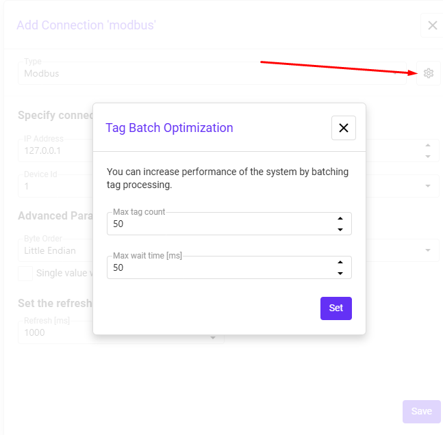
Batch optimization
Batch optimization means grouping multiple tags into a single Modbus request instead of reading or writing them one by one. This improves performance by reducing the number of requests, lowering communication overhead, and making data exchange faster.
- Max tag count – the maximum number of tags that can be grouped into one request.
- Max wait time [ms] – maximum time the system will wait to collect tags before sending the batch.
In short: larger batches = fewer requests and better efficiency, but possibly slightly slower response for individual tags.
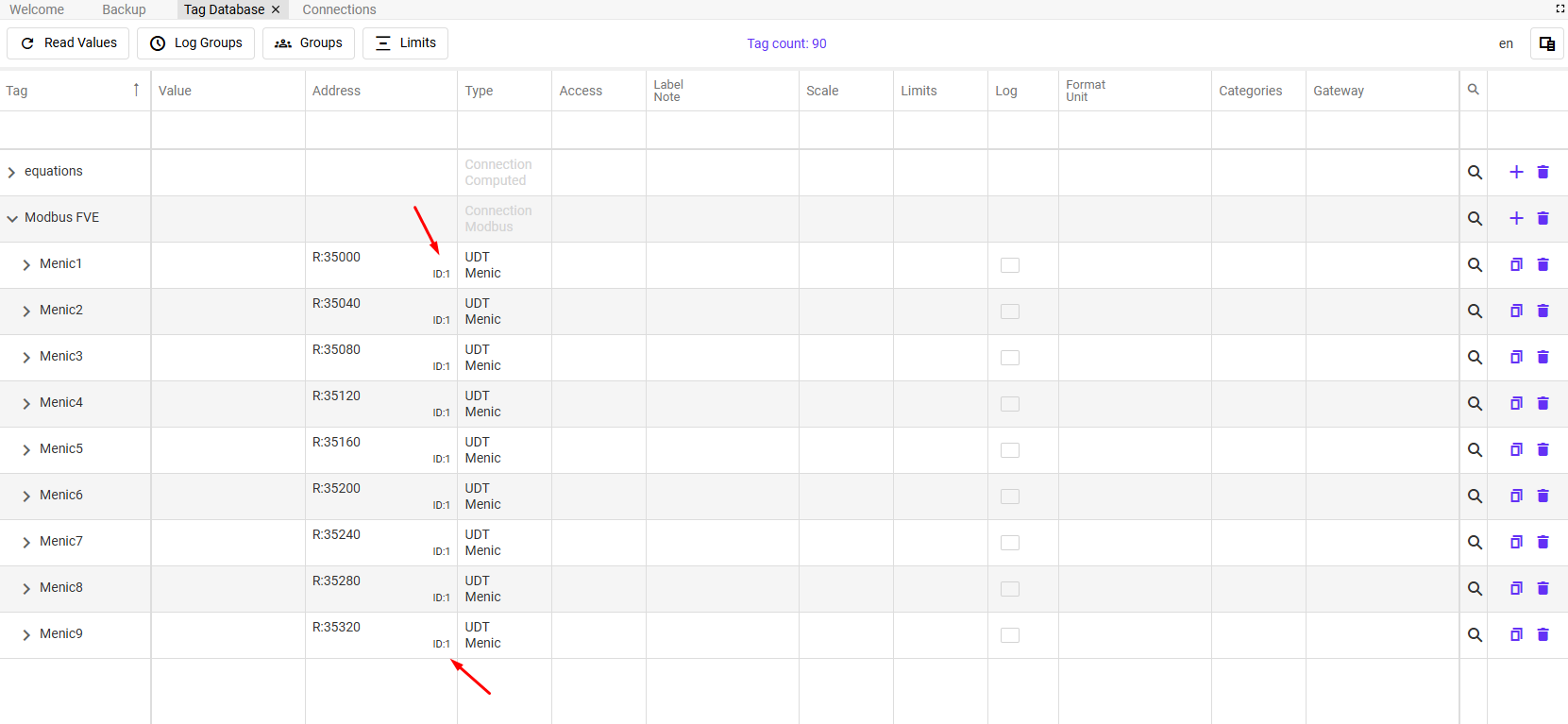
Device ID: Device ID can be changed in the address section in the tags database –
Example: If you have four power meters on the same line, you assign IDs like 1, 2, 3, and 4.